


Description
OTF-1200X-S-HPCVD is a compact 2" split tube furnace with an internal sample traveling system inside the processing tube. This allows the position & temperature control of the sample stage or crucible via touch screen digital controller. It is designed for multi-functional rapid thermal processing, such as hybrid physical-chemical deposition(HPCVD), rapid thermal evaporation (RTE), and as well Horizontal Bridgman Crystal Growth ( HDC) under various atmospheres for new-generation crystal research.
SPECIFICATIONS:
|
Split Tube Furnace
|
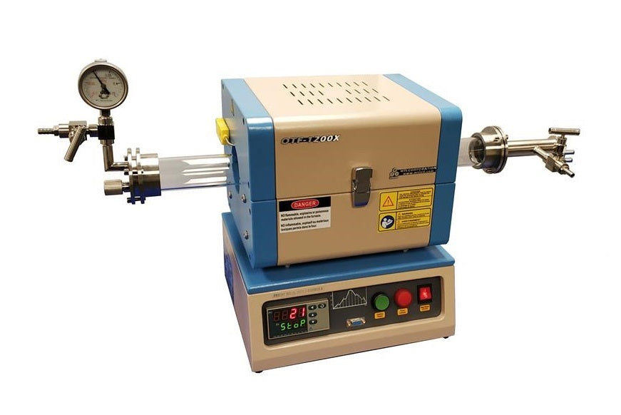  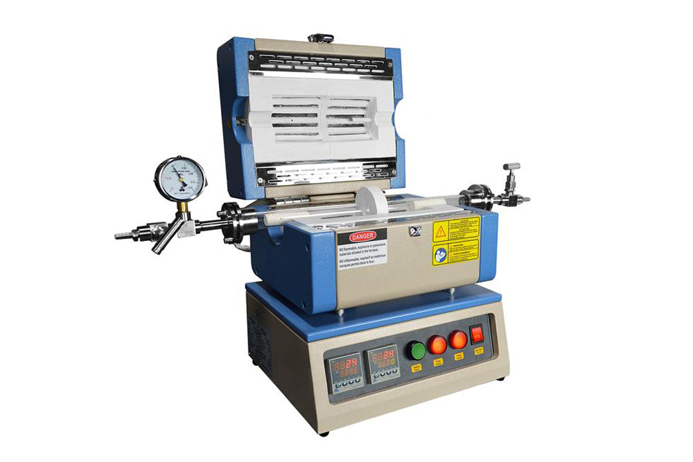 -- two-zone furnace -- two-zone furnace |
|||
|
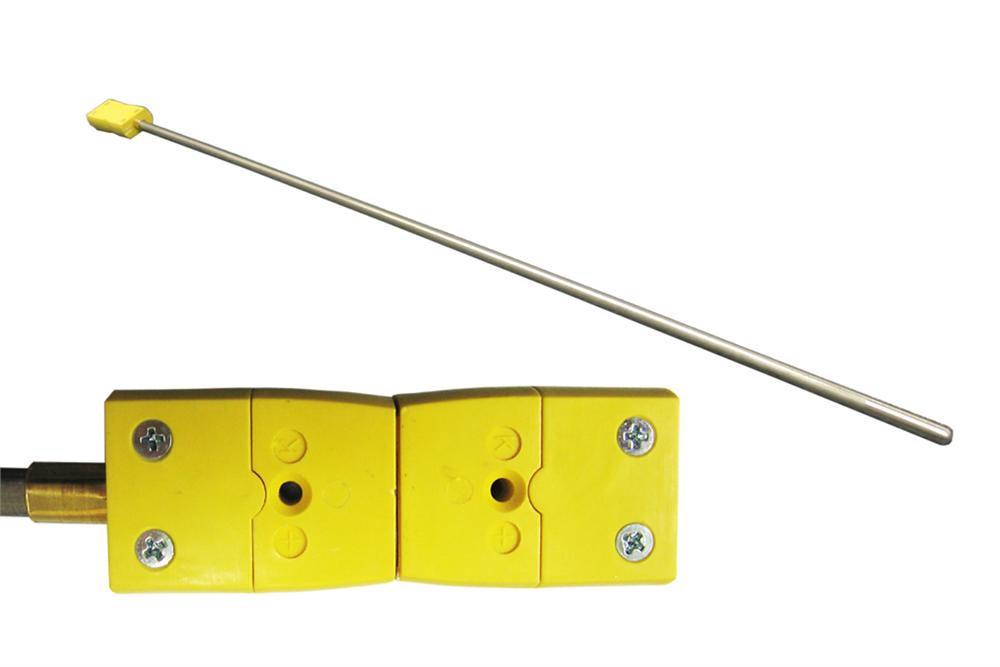
Temperature Control
|
 |
|||
|
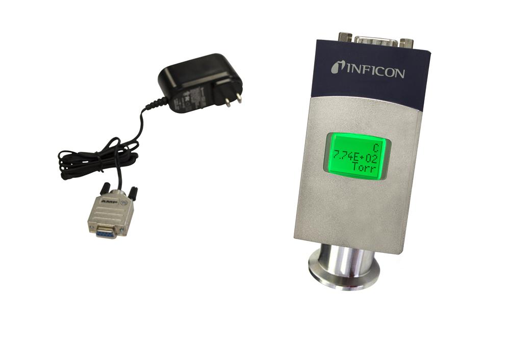
Vacuum Sealing
|
 (click the picture to see details ) (click the picture to see details ) |
|||
| Internal Traveling Mechanism & PLC Control Panel |
 Pic 1. Pic 1.  Pic 4. Pic 4. |
|||
| Max. Heating & Cooling Rate |
The max heating and cooling rate can be achieved by moving the sample into the pre-heated hot zone and moving the sample out from the hot zone. The typical ramp/cool rate is listed in below:
|
|||
|
Optional Parts |
|
|||
|
Laptop, software (Optional)
 
|
|
|||
|
Compliance |
|
|||
|
||||
| Application Notes |
This multi-functional furnace is suitable for the applications in below:
|


